Boom! The classic potato gun harnesses the combustion of flammable vapor. Show us your combustion spud gun and discuss fuels, ratios, safety, ignition systems, tools, and more.
-
Dumbascii
- Private 3

- Posts: 44
- Joined: Wed Nov 29, 2006 5:22 pm
-
Contact:
Wed Aug 22, 2007 8:44 pm
This is the ignitor used in my
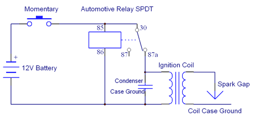
Taternator II. It can be made from cheap junkyard parts, any old mechanical ignition. When the button is pressed, current is sent to the coil through the normally-closed relay contacts. The relay is energized at the same moment, breaking the circuit to the ignition coil a split second later. The coil generates a spark when the magnetic field collapses. The condenser shunts the flyback voltage to ground, minimizing arcing inside the relay. The spark is beefy enough to jump three 1/8" gaps in series and is very reliable even under hybrid pressures. The battery does not need to be a car battery - just 12V.

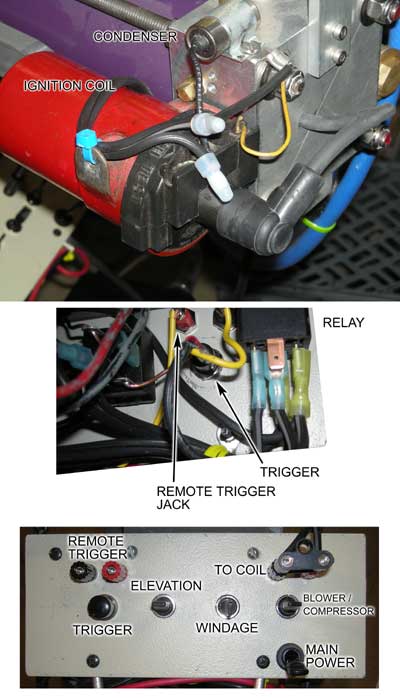
Edit: added photo below. Notice that the cases of the coil and condenser are well connected to the chassis. Sorry for the crappiness of the phto of the back of the control panel - it is difficult to reach without dismantling.

Last edited by
Dumbascii on Thu Aug 23, 2007 6:45 pm, edited 1 time in total.
-
shud_b_rite
- Specialist 2

- Posts: 290
- Joined: Tue Jan 30, 2007 7:10 pm
- Location: Auckland, New Zealand
Thu Aug 23, 2007 4:57 am
I agree, nice and simple setup. What sort of capacitor did you use (rating and value)? Isnt the condenser also supposed to oscillate the spark until all of the current dissipates so the spark lasts longer?
Airbeds... so many different uses
-
jimmy101
- Sergeant Major


- Posts: 3198
- Joined: Wed Mar 28, 2007 9:48 am
- Location: Greenwood, Indiana
- Has thanked: 5 times
- Been thanked: 15 times
-
Contact:
Thu Aug 23, 2007 11:37 am
For this type of circuit the capacitor is the condensor from the old automotive points/rotor setup.
IIRC, the cap is there to protect the points by minimizing arcing across them. In this circuit, I believe the cap will minimize arcing across the relay's contracts. The cap doesn't contribute to the power of the circuit, indeed I believe it lowers the power by a small amount.
Surpressing sparking at the contacts in a distributior also reduces radio noise caused by the sparks.
The cap can be eliminated and the circuit should work fine. The life of the relay may be shortened a small amount, and the ciruit will make more radio frequency noise but heck, the spark gap itself is a pretty good radio transmitter.
A photo would be nice, then move to the "How to" section.
-
Dumbascii
- Private 3

- Posts: 44
- Joined: Wed Nov 29, 2006 5:22 pm
-
Contact:
Thu Aug 23, 2007 6:48 pm
jimmy101 wrote:For this type of circuit the capacitor is the condensor from the old automotive points/rotor setup.
Exactly - nothing to buy.
jimmy101 wrote:The cap can be eliminated and the circuit should work fine. The life of the relay may be shortened a small amount, and the ciruit will make more radio frequency noise but heck, the spark gap itself is a pretty good radio transmitter.
Without it, the arc at the relay contacts is very severe. I had a clear relay for a while that let you see the arc. It also had problems pulling the relay without the condenser. Radio noise is not really an issue because it is a single arc - not a continuous buzz like in a real ignition.
jimmy101 wrote:A photo would be nice, then move to the "How to" section.
I edited in a photo, but I'm not sure how to move the post to a different forum category.


